6-Pin vs 9-Pin Truck Diagnostic Connector: Key Differences Explained

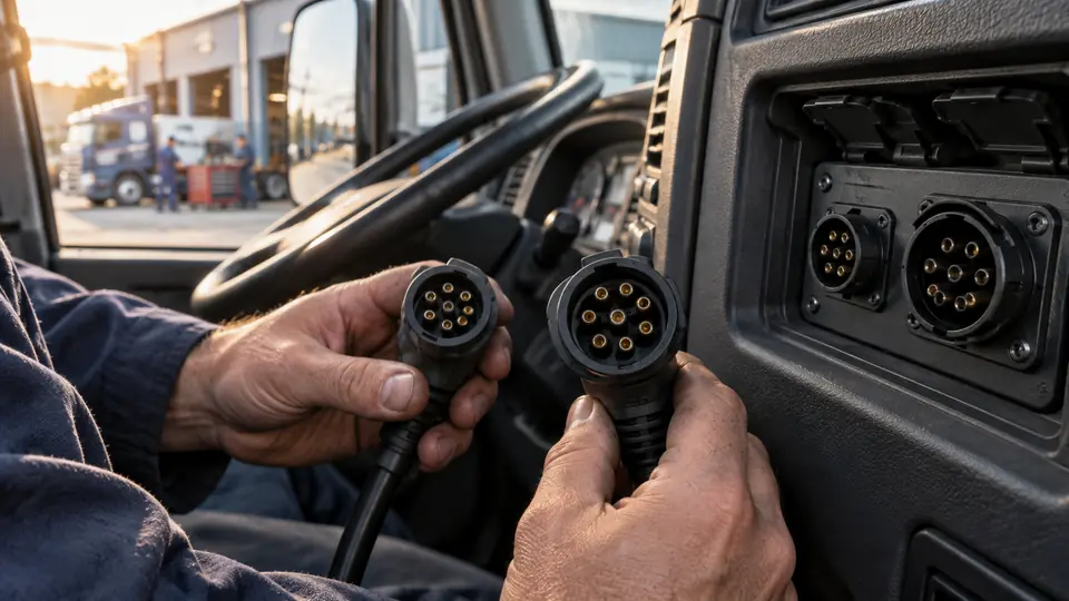
The 6-pin vs 9-pin truck diagnostic connector distinction usually reflects different generations of heavy-duty vehicle networks. A 6-pin connector is commonly associated with older J1708/J1587 systems, while a 9-pin connector is commonly associated with J1939 networks on newer or mixed-network trucks. The connector shape alone does not prove which protocol, ECU, or diagnostic function the truck supports.
For accurate communication, the scanner, cable, protocol, software, and vehicle system must all be compatible. An adapter that physically fits the truck may provide only the electrical connection. It does not automatically convert one communication protocol into another or guarantee access to every control module.
6-Pin and 9-Pin Connectors at a Glance
| Connector | Common diagnostic context | Typical practical issue |
|---|---|---|
| 6-pin heavy-duty connector | Often associated with J1708/J1587 on older commercial vehicles | May require a scanner or adapter that supports older heavy-duty communication systems |
| 9-pin heavy-duty connector | Often associated with J1939, with some applications also carrying older network signals | J1939 support does not guarantee access to every ECU or service function |
| 16-pin OBD2 connector | Commonly used in passenger vehicles and some newer commercial applications | A 16-pin shape does not automatically establish standard passenger-car OBD2 functionality |
These are common patterns rather than universal rules. Truck manufacturers, model years, engine suppliers, and body builders may use different network arrangements. The service documentation for the exact truck remains the authoritative source for connector and protocol identification.
What a 6-Pin Truck Diagnostic Connector Usually Indicates
A 6-pin Deutsch-style connector is frequently found on older heavy-duty trucks and equipment that use J1708 and J1587 communication. J1708 describes a vehicle data link, while J1587 defines messages and parameters commonly transmitted over that link.
A compatible diagnostic tool may use this connection to retrieve engine, transmission, ABS, or other supported fault information. Actual module access varies by truck and scanner coverage. A 6-pin connector does not establish that every listed system is available.
Some 6-pin connectors may also appear in applications with different wiring or network arrangements. For that reason, the connector should be treated as a physical clue, not a complete protocol identification.
What a 9-Pin Truck Diagnostic Connector Usually Indicates
The 9-pin Deutsch connector is widely associated with J1939 communication on heavy-duty trucks. J1939 uses a controller area network structure and carries messages such as parameter data and diagnostic information between electronic control units.
A 9-pin connection commonly provides access to J1939-based diagnostics when the scanner supports the truck, engine, ECU, and required software. Some vehicles use a 9-pin connector that also includes older J1708/J1587 circuits, creating a mixed-network diagnostic point. Other vehicles may wire the connector differently.
A 9-pin connector therefore does not guarantee complete J1939 diagnostics. It also does not prove that the scanner can reach the transmission, ABS, body controller, aftertreatment system, or other modules. Those capabilities depend on the vehicle and ECU coverage provided by the diagnostic platform.
Why the Connector Difference Matters
The connector affects the physical connection between the truck and the diagnostic interface. The communication protocol determines how data travels across the network. Diagnostic software determines how supported data is interpreted and which functions are available.
These layers must work together:
- Physical connector: The plug and wiring interface used at the truck.
- Communication protocol: The network language, such as J1708/J1587 or J1939.
- Diagnostic interface: The cable, adapter, or VCI that communicates with the truck.
- Scanner software: The application that identifies modules, retrieves faults, and displays data.
- Vehicle and ECU coverage: The specific truck, model year, engine, and module combinations supported.
- Diagnostic or service function: The operation being requested, such as code reading, live data, an active test, or a reset.
A cable can fit correctly while the scanner remains unable to communicate. This may happen because the tool lacks the required protocol, the application is unsupported, the selected vehicle information is incorrect, or the relevant ECU is outside the software coverage.
Can a 6-Pin Scanner Work With a 9-Pin Truck?
Sometimes, but a simple plug adapter is not enough to establish compatibility. The scanner must support the protocol used by the truck, and the adapter must correctly route the required power, ground, and communication circuits. A tool intended only for J1708/J1587 may not communicate with a J1939-only application.
A 9-pin truck may also contain older network circuits, so a scanner that supports both J1939 and J1708/J1587 may communicate through the same connector. That arrangement is application-dependent and should be confirmed in the scanner’s coverage information.
The same principle applies in the opposite direction. A 9-pin-capable scanner may require a suitable 6-pin adapter and support for the older network used by the truck. J1939 capability by itself does not establish J1708/J1587 capability.
How to Identify the Correct Connection
Before connecting a scanner, collect the vehicle information and verify the diagnostic requirements rather than relying on connector appearance alone.
- Identify the truck. Record the make, model, model year, engine make, engine model, and any available ECU or system information.
- Inspect the connector. Confirm whether the diagnostic port has six, nine, or another number of contacts. Check for bent, pushed-back, corroded, or damaged terminals.
- Check the vehicle documentation. Service information may identify the network, connector wiring, and modules connected to the port.
- Verify scanner coverage. Confirm support for the truck and engine combination, not merely the connector type or truck brand.
- Confirm the adapter. Check that the cable matches the connector and is intended for the scanner interface and required protocol.
- Select the correct application. Use the scanner’s vehicle, engine, or system selection as directed. An incorrect selection can prevent communication or provide incomplete coverage.
Common 6-Pin and 9-Pin Diagnostic Problems
| Symptom | Possible explanation | Next check |
|---|---|---|
| The scanner does not power on | Missing connector power, poor ground, damaged cable, or an interface fault | Check the connector’s power and ground circuits with the applicable wiring information, then inspect the cable and interface |
| The scanner powers on but cannot connect | Incorrect vehicle selection, unsupported protocol, poor terminal contact, or missing ECU coverage | Confirm the truck details, protocol support, adapter type, and module coverage |
| Engine data is available but another module is missing | The tool may support the engine ECU without supporting ABS, transmission, body, or aftertreatment modules | Review system-level coverage for the exact vehicle and model year |
| A 9-pin adapter fits but communication fails | The connector may use a different network arrangement, or the adapter may provide only physical pin access | Verify the wiring, protocol, interface, and software requirements |
| Faults can be read but a service function is unavailable | Diagnostic access and service-function support are separate capabilities | Confirm support for the specific reset, active test, regeneration, or other requested function |
6-Pin vs 9-Pin: Choosing the Right Adapter
Select an adapter based on the truck’s actual connector and communication requirements. A 6-pin-to-9-pin cable may solve a physical connection problem, but it may not provide protocol conversion. Many adapters are passive wiring hardware, so the scanner still needs native support for the network used by the vehicle.
Check the following before using an adapter:
- The connector type on the truck.
- The interface connector accepted by the scanner or VCI.
- The protocol or protocols supported by the vehicle.
- Whether the adapter carries the required power, ground, and data circuits.
- Whether the scanner software supports the target truck, engine, ECU, and system.
- Whether the required function is code reading, live data, an active test, or a service operation.
What the Connector Does Not Tell You
The number of pins does not identify the truck’s complete diagnostic capability. It does not prove that the vehicle uses a particular model-year network, that every ECU is connected to the diagnostic port, or that a scanner can perform advanced service operations.
Reading a fault through either connector also does not prove that a component has failed or that clearing the fault will repair the condition. Fault information is a starting point for checking related data, wiring, connectors, system operation, and vehicle-specific service information.
For a reliable connection, match the truck, engine, ECU, protocol, connector, scanner interface, software, and requested function. That layered check is more dependable than choosing a cable from the connector shape alone.

- Caleb
Caleb writes about heavy-duty truck scanners, diagnostic tools, vehicle compatibility, and related technologies for Best Truck Scanners. His work focuses on making product specifications and diagnostic features easier to understand and compare.
- Best J1939 Diagnostic Adapter: 9 Picks in 2026 November 14, 2026
- 6-Pin vs 9-Pin Truck Diagnostic Connector: Key Differences Explained November 12, 2026
- Best Scanner for Cummins X15: 9 Picks in 2026 November 10, 2026
- Best Scanner for PACCAR MX-13: 9 Picks in 2026 November 8, 2026
- SPN vs FMI: Understanding Heavy-Duty Diagnostic Fault Codes November 6, 2026